A lot of what it takes to go break the world record at Battle Mountain is the efficiency of the external aerodynamic shape. A huge amount of work had been done to design and optimize the shape of Eta prior to the start of summer to ensure we get the least drag on the vehicle. In this post we will outline the steps we went through in the design process.

The design of Eta’s shape was conducted before the beginning of the summer. Trevor was involved in the development of an aerodynamic shape optimization process which he’d undertaken for his undergrad thesis under Professor David Zingg at the University of Toronto Institute of Aerospace Studies. The process involves having a user supply an initial shape as well as a prescribed pressure distribution over the body and then allowing an optimizer to manipulate many control points over the vehicles’ surface to find the shape of a body which matches that pressure distribution. The process solves the Euler equations around the vehicle at a design point and the optimizer computes the gradient of the design space using an adjoint sensitivity analysis scheme. Using the adjoint method, the computational cost of a gradient calculation is effectively independent of the number of design variables. This is very powerful for shape optimization because it means many control points can be used to parametrize a surface to a very arbitrary shape.

Control point distribution over Eta used for the optimizations. Use of the adjoint method allows the shape to be parametrized by many control points for optimization.
So why is the pressure distribution over the vehicle so important? The pressure distribution is directly related to the stability of the laminar boundary layer, the induced drag on the body and the onset of flow separation over the body, three important things we design for in order to minimize our drag at Battle Mountain.
Pressure Profile Design
As mentioned, the design process is based upon the pressure distribution over the surface of Eta. Here we will briefly describe the rationale which went into the design of Eta’s pressure profiles.
The most important part of making our vehicle faster than an ordinary bicycle is by eliminating flow separation over the body. Doing this can decrease the drag over a given size object by over an order of magnitude! Flow separation is caused when an adverse pressure gradient (increasing pressure) is too steep within the pressure recovery region at the back of our vehicle. To design the pressure profiles of the vehicle to eliminate flow separation, the Stratford-Smith criterion was used. This criterion is an analytic formulation to determine when the flow is on the verge of separation based upon the pressure gradient along streamlines.
Once the separation pressure drag over the vehicle is eliminated, the shear surface drag on the vehicle then becomes the largest drag component we see on the vehicle. This is the drag acting tangentially to the surface of the vehicle caused by the viscosity of the air moving across it. The shear drag on the vehicle is determined by the state of the boundary layer over the surface. The boundary-layer is a small region on the surface of the vehicle where the viscous effects of the air moving over the vehicle surface is important. The boundary layer grows to about a centimetre thick at the trailing edge of our vehicles and can accounts for the vast majority of our aerodynamic drag. The boundary-layer begins laminar at the nose but may eventually destabilize into a turbulent boundary layer which has many times more drag. Obviously we would like the pressure profiles for Eta to be designed for extensive runs of laminar flow.
To design for laminar flow, a favourable pressure gradient (decreasing pressure) along surface streamlines is desirable to assist in the stability of the laminar boundary layer and prevent it from transitioning to turbulence. In the laminar region, the shape of the pressure profiles are modelled based upon two-dimensional airfoils are designed for extensive runs of laminar flow (most notably NACA 6-Series airfoils). These typically follow a constant favourable (negative) pressure gradient which allows for a similar amount laminar flow across various angles of attack.
Another thing to mention about extensive runs of laminar flow is its contribution to reducing flow separation. Greater amounts of laminar flow substantially reduces the momentum boundary-layer thickness (a measure of how much of the flow’s momentum is trapped in the boundary-layer) and allows for a shorter tail and a more aggressive pressure recovery. Another reason why laminar flow will help reduce Eta’s drag.
All put together, the pressure profiles Eta was designed for boast a linear laminar flow region combined with a Stratford pressure recovery. These “ideal” pressure profile curves are seen below, followed by the pressure distribution projected onto our original geometry:

Ideal surface streamline pressure distributions for the first iteration of Eta’s shape optimizations. Red curves are over the bottom of the vehicle to Blue curves over the top.

Ideal pressure distribution over Eta seen projected on the original geometry of iteration 1. The optimizer modifies the shape of the vehicle to try and match this pressure distribution.
Shown above is the pressure distribution seen on the original geometry I’d made for Eta. The optimizer then worked away to adjust the shape of the bike to actually meet this distribution.
The Results of the first Iteration
The first optimization met the pressure distribution of the vehicle quite well even though only subtle changes were made to the geometry. Seen below is the shape after this stage:

Top view of Eta’s shape after iteration 1.

Sideview of Eta’s shape after iteration 1.
As you can see, the first iteration Eta is quite small and squat, sporting a wetted area of only 3.51m^2. However, after some trade studies concerning a Battle Mountain race simulation, the use of 406 tires was weighed against 650c tires. Although using 650c tires increases the wetted area of the vehicle (by increasing vehicle height, tail length and nose width), it was decided this was still a more optimal configuration due to its reduction in rolling resistance which can be achieved with 650c tires and a more upright pilot position where more power can be delivered. Thus a second iteration was considered.
The Second Iteration
We began the initial shape for the second iteration by modifying the curves of the first iteration vehicle to accommodate the larger wheels. We then progressed through many subsequent CFD iterations, getting the surface streamlines closer to ideal pressure profiles with the similar properties as described above. We did this “massaging” the shape of the vehicle to change the distribution closer to what we wanted. Our team has had a lot of experience modifying shapes like this through the design of both our 2011 vehicle Vortex and our 2012 vehicle Bluenose. Through these iterations we were able to get the shape quite close to the final design but we ran it through the optimizer again with the goal of an additional 10cm of laminar flow and to sort out a few surface oddities. The new “ideal” pressure distribution for the second optimization iteration is shown below.

Ideal surface streamline pressure distributions for the first iteration of Eta’s shape optimizations. Red curves are over the bottom of the vehicle to Blue curves over the top.

Ideal pressure distribution over Eta seen projected on the original geometry of iteration 2. The optimizer modifies the shape of the vehicle to try and match this pressure distribution.
Upon completion of this optimization process for the second iteration, the shape was effectively complete, however since surface curvature continuity constraints had not been successfully integrated into the optimization process, the shape output by the optimizer needed to be tweaked to ensure its curvature was smooth before being sent off for machining. We made these final adjustments and prepared the CAD model for machining at Plasterform. Seen below is the final CFD results for Eta as well as some pictures of its shape:

Streamlines over the final shape of Eta.
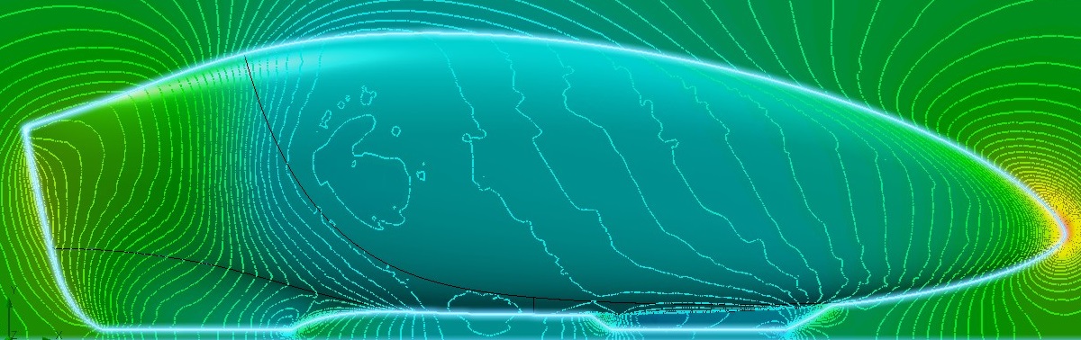
Final pressure distribution over the surface of Eta.

Pressure distribution over Eta’s surface streamlines. Blue curves are over the bottom of the vehicle to Red curves which are over the top.
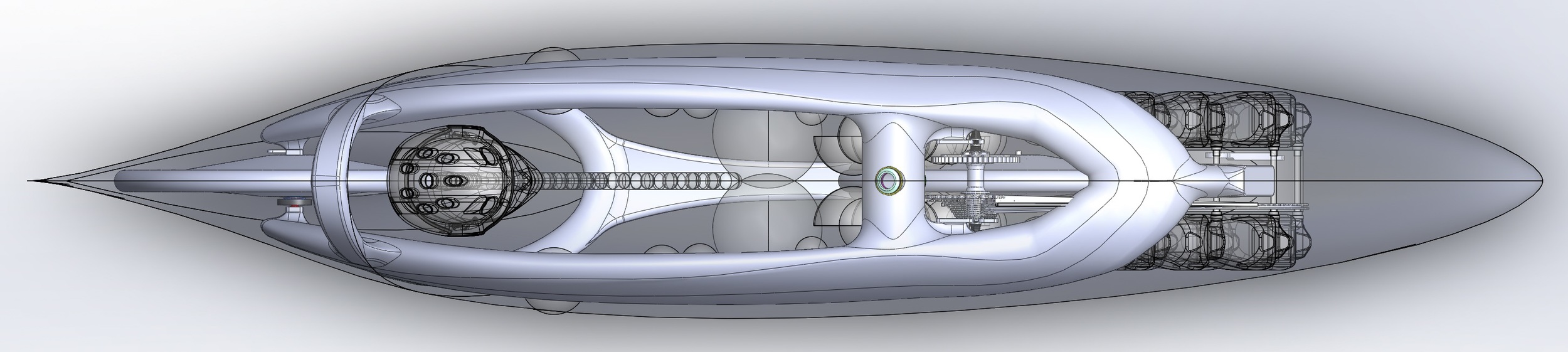
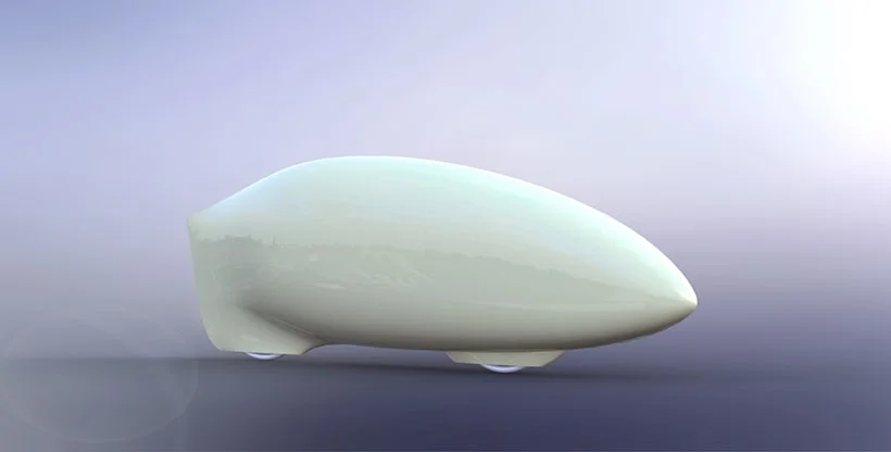
Top view of the final shape of Eta.

Side view of the final shape of Eta.

Eta mould stock at Plasterform.
Plaster form did a fantastic job cutting out the shape for our mould plug on their large 5-axis CNC mill.
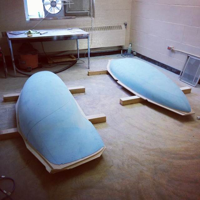
Eta’s machined plugs.
Next steps are to prep the plug and form some moulds on it! Stay tuned for updates! 😉